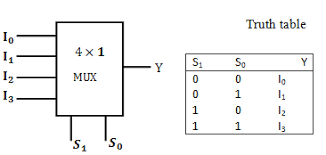
MULTIPLEXER is a logic circuit which accepts
many inputs,but selects only one input to be passed
on to the output.It is sometimes referred to as a
data selector,since it selects only one of the
inputs.The selection of the input to be passed is
done by a set of Control Signals known as the
Select inputs.The value on these select inputs will
determine the input that is to be passed on to the
output.Multiplexer is also known as MUX
 NO OF THE SELECT LINES ARE EQUALS TO:
n=2^x,
where x: no of select lines(actually these are controller lines)
n: No of inputs


LOGIC DIAGRAM OF MULTIPLEXER
4 to 1 Multiplexer
For understanding the multiplexer further, we are selecting a 4-to-1 Multiplexer. There are many others like 2-to-1, 8-to-1, 16-to-1 multiplexers etc. In this multiplexer, the details are the following:
Inputs
As the name indicates, there are 4 input bits. They are D0, D1, D2 and D3.
Output
The number of output is one and is referred as Y.
Control Bits
Two control bits are used here, A and B. This will decide which input
bit should have to be selected. The output clearly depends on this
control bits.

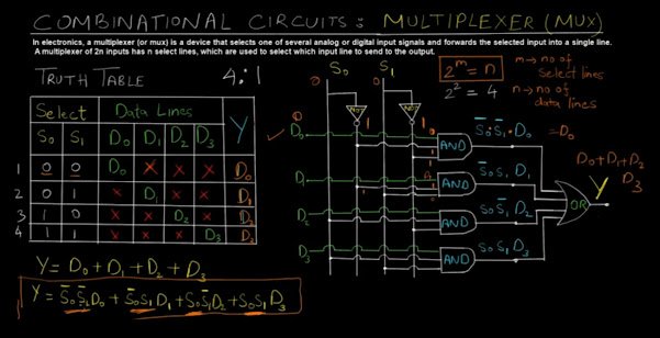
The multiplexer circuit is shown above. If the condition AB = 00, the top most AND gate is enabled (shown in figure above). At this time, all the other three AND gates are in disabled condition. So, input bit D0 is selected and transmitted as output. Thus, Y = D0.
If the condition AB = 11, every other AND gates are disabled excluding the bottom most AND gate. So, input bit D3 is selected and transmitted as output. Thus, Y = D3.
The examples of multiplexers are IC 74153, IC 45352 (4-to-1 multiplexers), IC 74150 (16-to-1 multiplexer)
Applications of Multiplexer
Multiplexers are implemented in several fields where there is a necessity of transmitting large amount of data with use of single line.
Computer Memory
In computer, the huge quantity of memory is implemented by means of multiplexers. It also has advantage of reduction in number of copper lines which are used for the connection of memory to other parts in the computer.
Communication System
Multiplexer is implemented in this system to increase efficiency. Using a single transmission line, various types of data (video, audio etc) are transmitted at the same instant.
Telephone Network
Here, the multiple audio signals are brought into a single line and transmitted with the implementation of multiplexer. By this method, the numerous audio signals are made isolated and ultimately the recipient will receive the required audio signals.
Computer System of a Satellite Transmission
Multiplexers are implemented for the data signals to be transmitted from space craft or computer system of satellite to the earth by means of GPS.
 NO OF THE SELECT LINES ARE EQUALS TO:


No comments:
Post a Comment