
CHECK OUT THE STATEMENTS WRITTEN ON RIGHTMOST SIDE
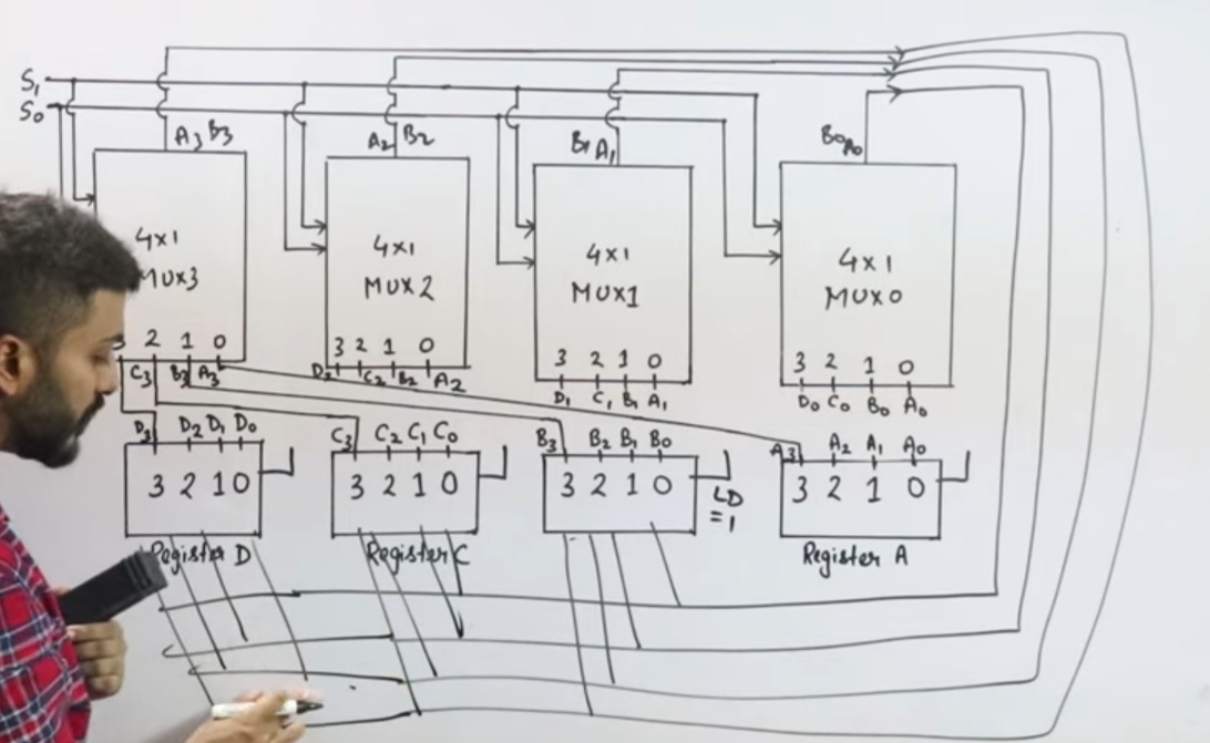
The construction of this bus system for 4 registers is shown above. The bus consists of 4×1 multiplexers with 4 inputs and 1 output and 4 registers with bits numbered 0 to 3. There are 2 select inputs S0 and S1 which are connected to the select inputs of the multiplexers.
The output 1 of register A is connected to input 0 of MUX 1 and similarly other connections are made as shown in the diagram. The data transferred to the bus depends upon the select lines. A table for the various combinations of select lines is shown below.
As we can see that when S1S0=00, register A is selected because on 00 the 0 data inputs of all the multiplexers are applied to the common bus.
Since the 0 data inputs of all the multiplexers receive the inputs from the register A, thus register A gets selected. Similarly for other combinations of S1S0 other register are selected.
Note-
No. of multiplexers needed = No. of bits in each register


No comments:
Post a Comment